
PIONEER SATELLITE VISUALIZATION
 View Image Only

Project Overview
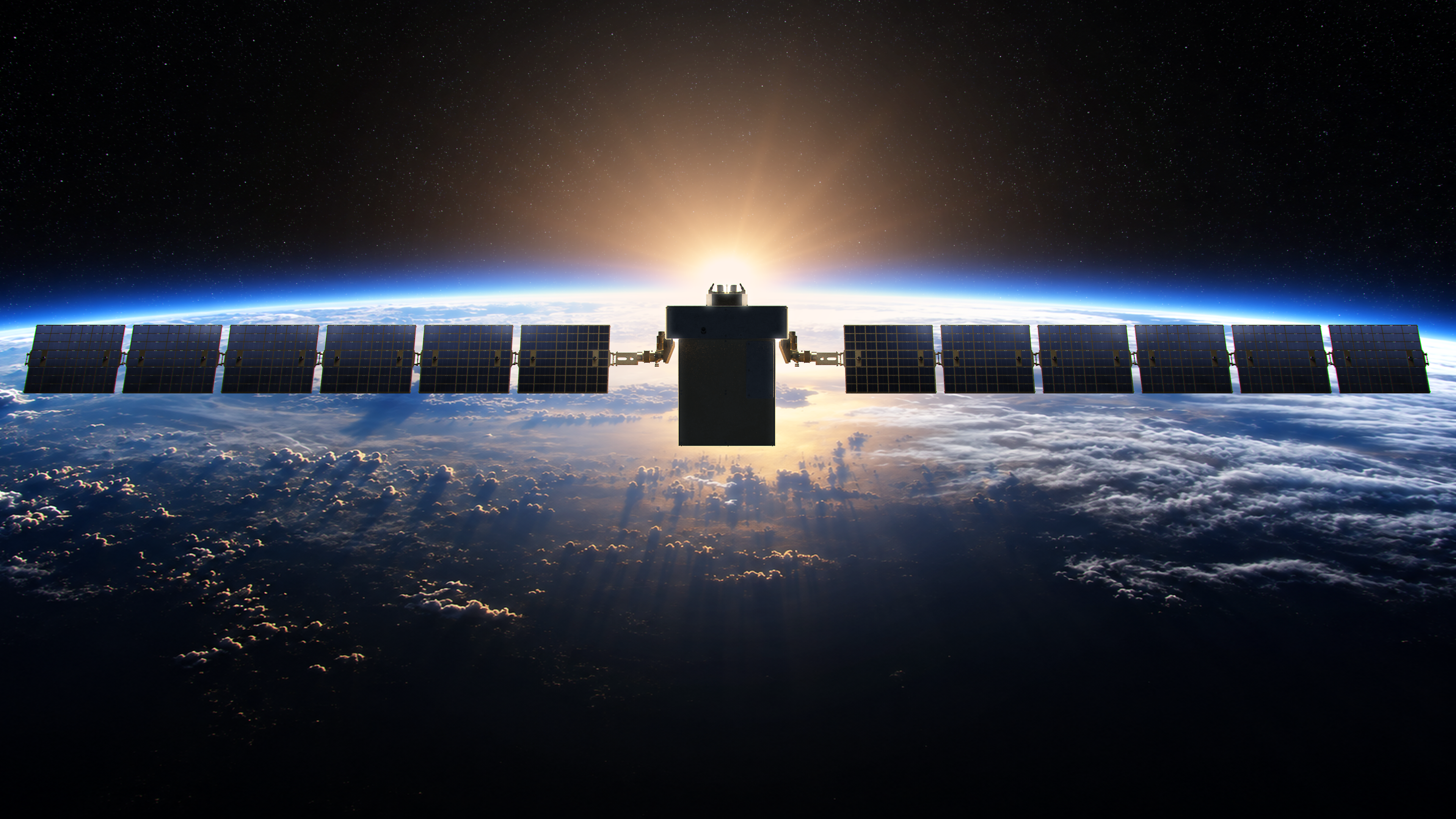
PIONEER is a modular Earth-orbiting spacecraft built around a compact central bus and a high-output dual-wing solar power system. Its long-span architecture balances sustained power generation with a tightly packaged service module designed for stable operation, straightforward systems access, and efficient deployment.
This visual record follows PIONEER from orbital operation through detailed configuration review. Cinematic mission imagery establishes scale and purpose, while the orthographic and isometric studies document the exterior systems, structural relationships, and deployment geometry that define the spacecraft.
On-Orbit Operations
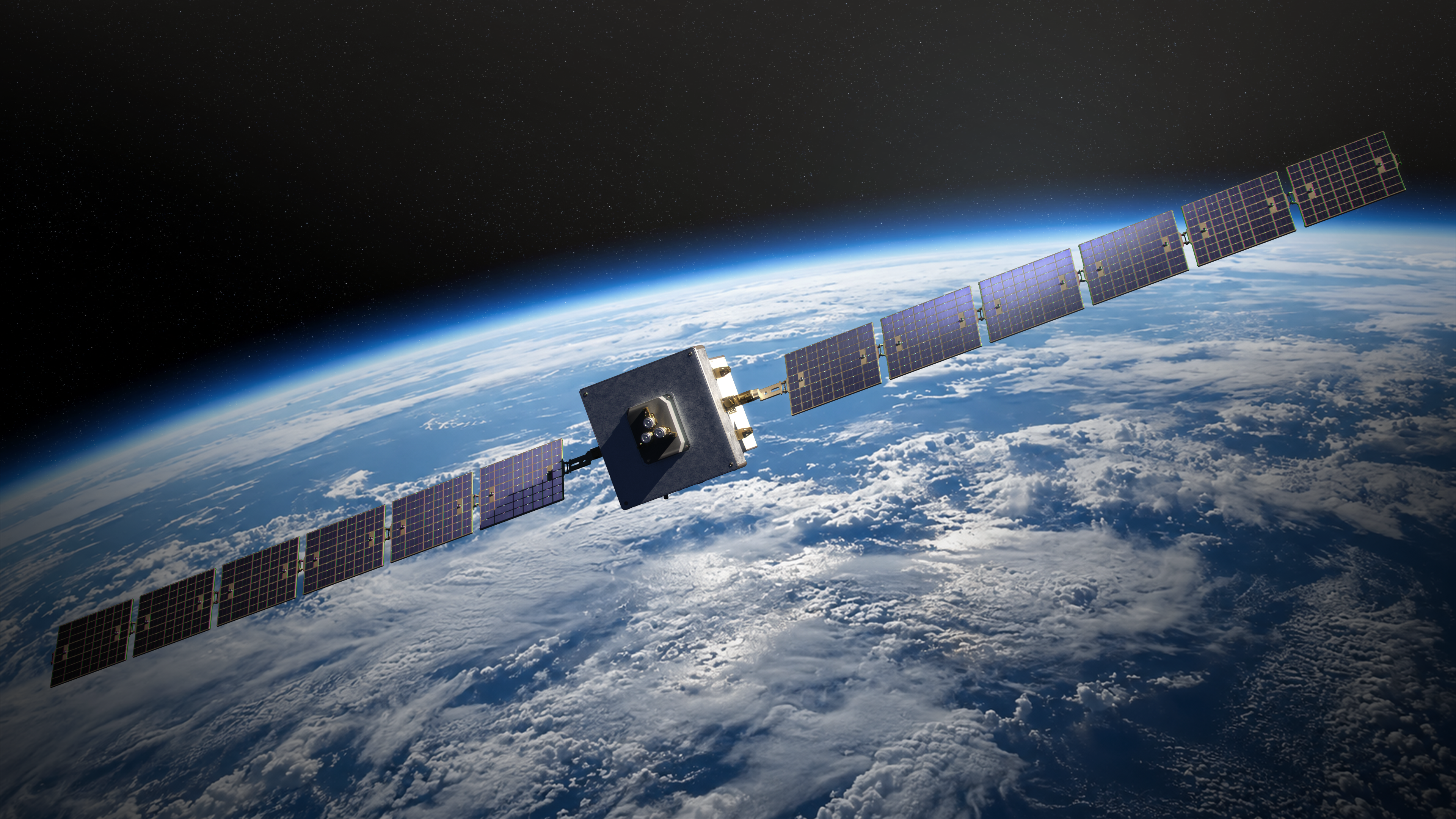
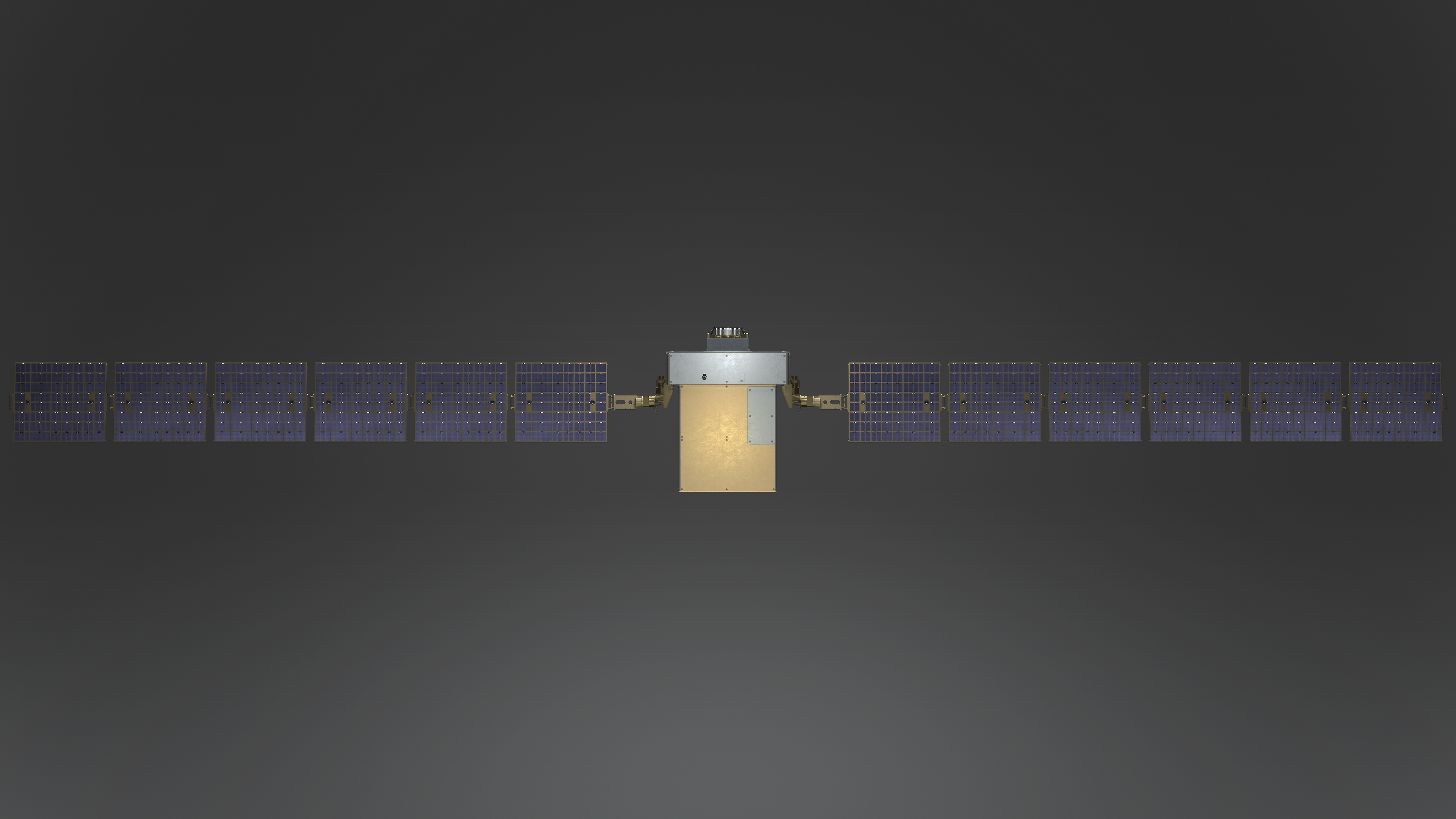
With both photovoltaic wings fully deployed, PIONEER presents a stable, symmetrical operating profile in Earth orbit. The compact bus remains centered between the arrays while the segmented panel system provides the broad collection area required for continuous mission power.
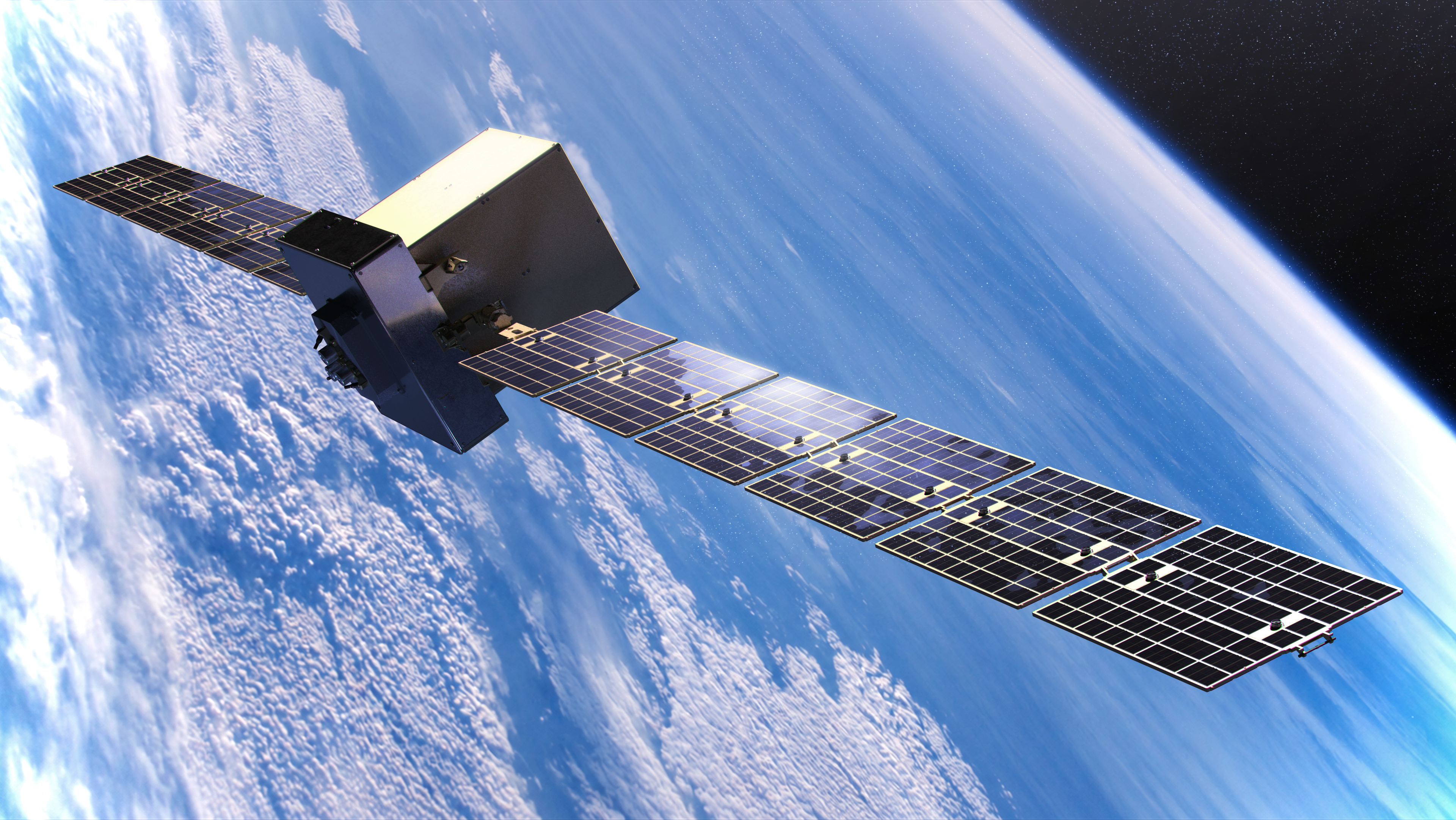
The orbital views emphasize attitude, array orientation, and the relationship between the vehicle and Earth. Sunlight across the panel surfaces and metallic bus makes the spacecraft configuration immediately readable while preserving the sense of altitude, scale, and operational purpose.
PIONEER Demonstration
This demonstration brings the complete PIONEER presentation into motion, showing how the spacecraft reads as an integrated orbital system rather than a collection of isolated components. The sequence connects its operating silhouette, deployed power architecture, materials, and technical configuration in a single concise program overview.
Solar Array and Power Architecture
PIONEER's power system is organized as two mirrored array wings extending from articulated yokes on the central bus. Each wing is divided into repeatable photovoltaic sections joined through a controlled deployment structure, allowing the full collection surface to launch in a compact state and establish a rigid operating span once on orbit.
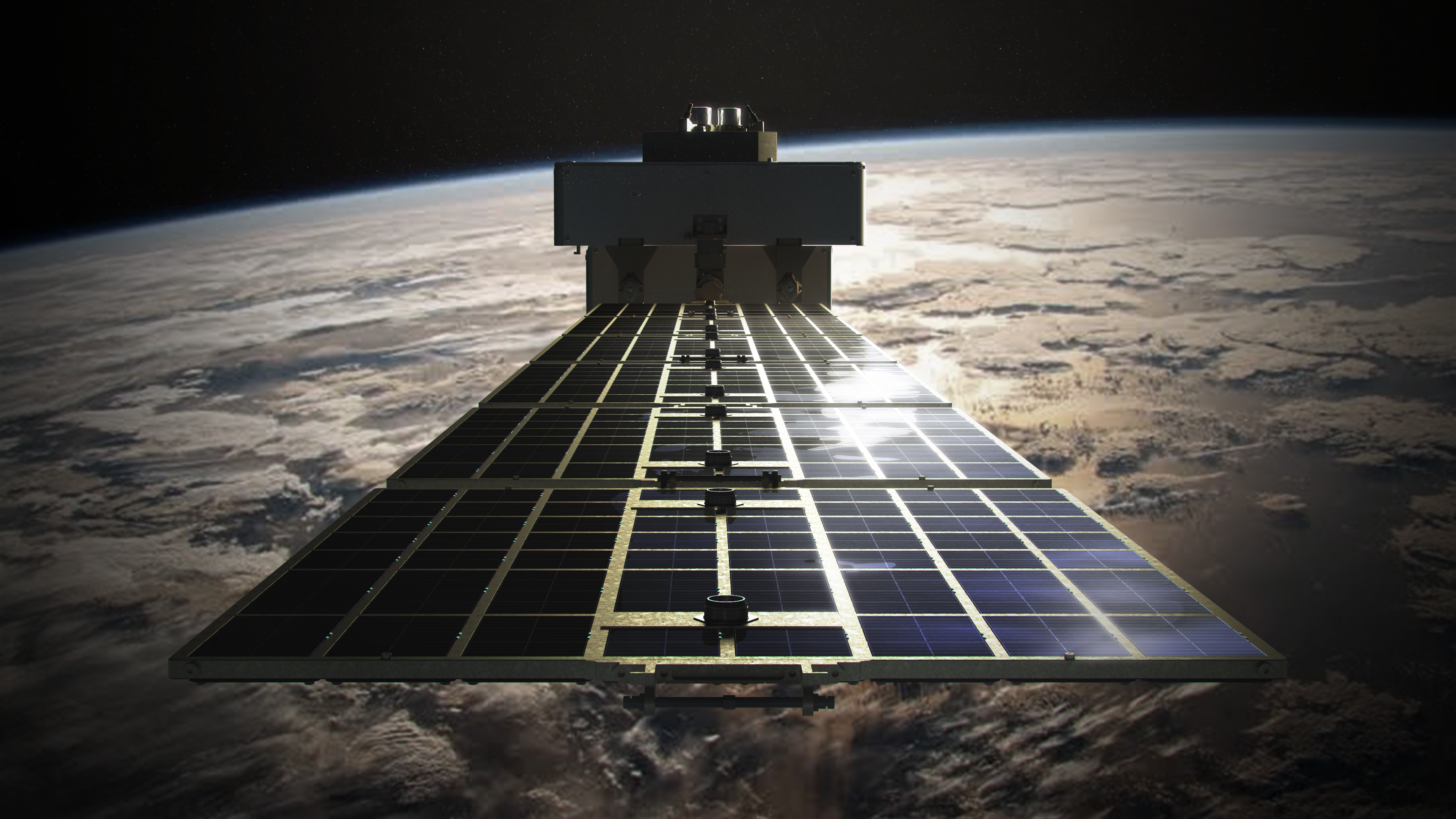
The repeated panel geometry, exposed hinge hardware, and restrained surface treatment keep the power architecture visually legible from close range while maintaining the durable, flight-ready character of the complete vehicle.
External Configuration Schematic
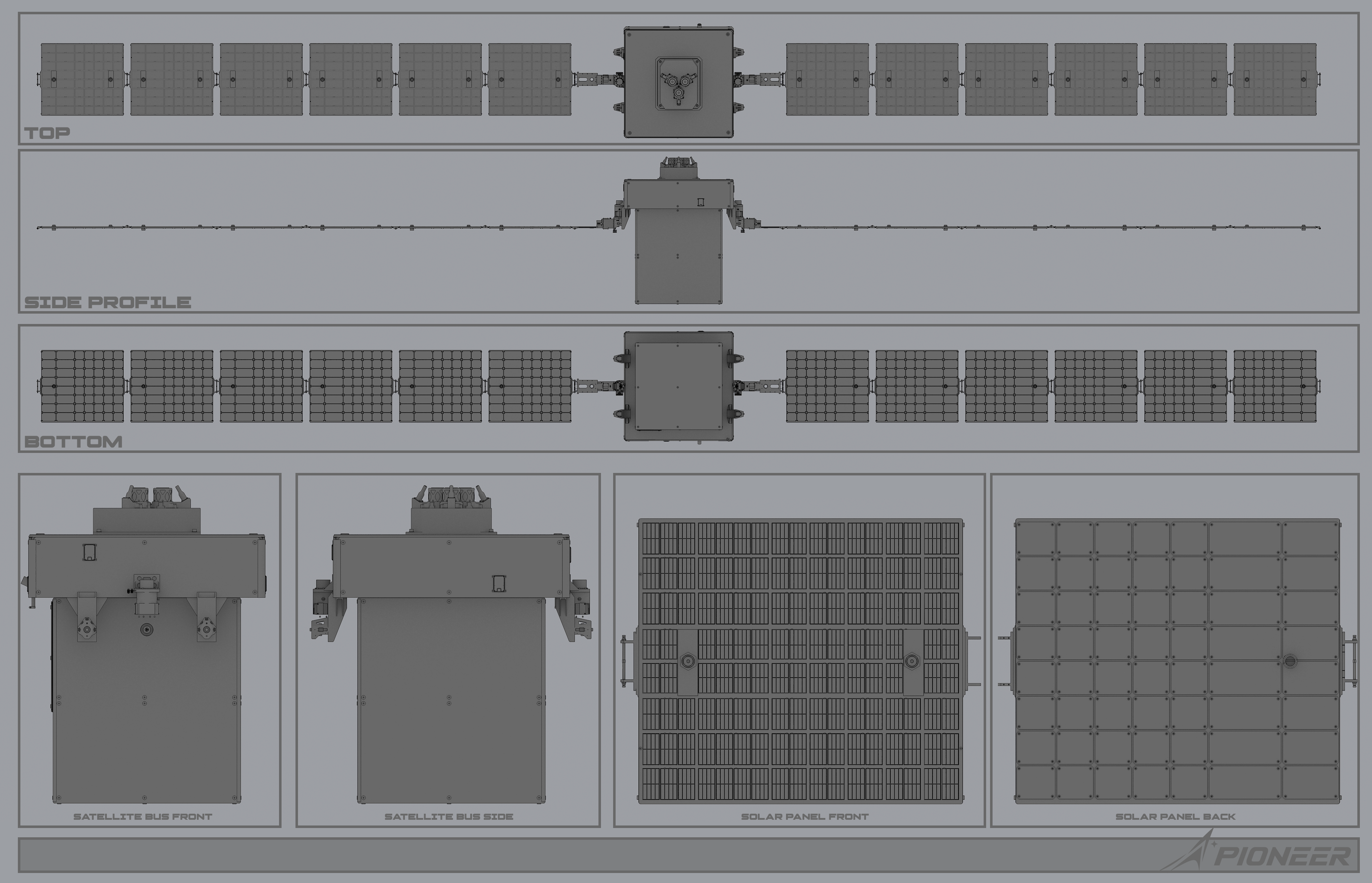
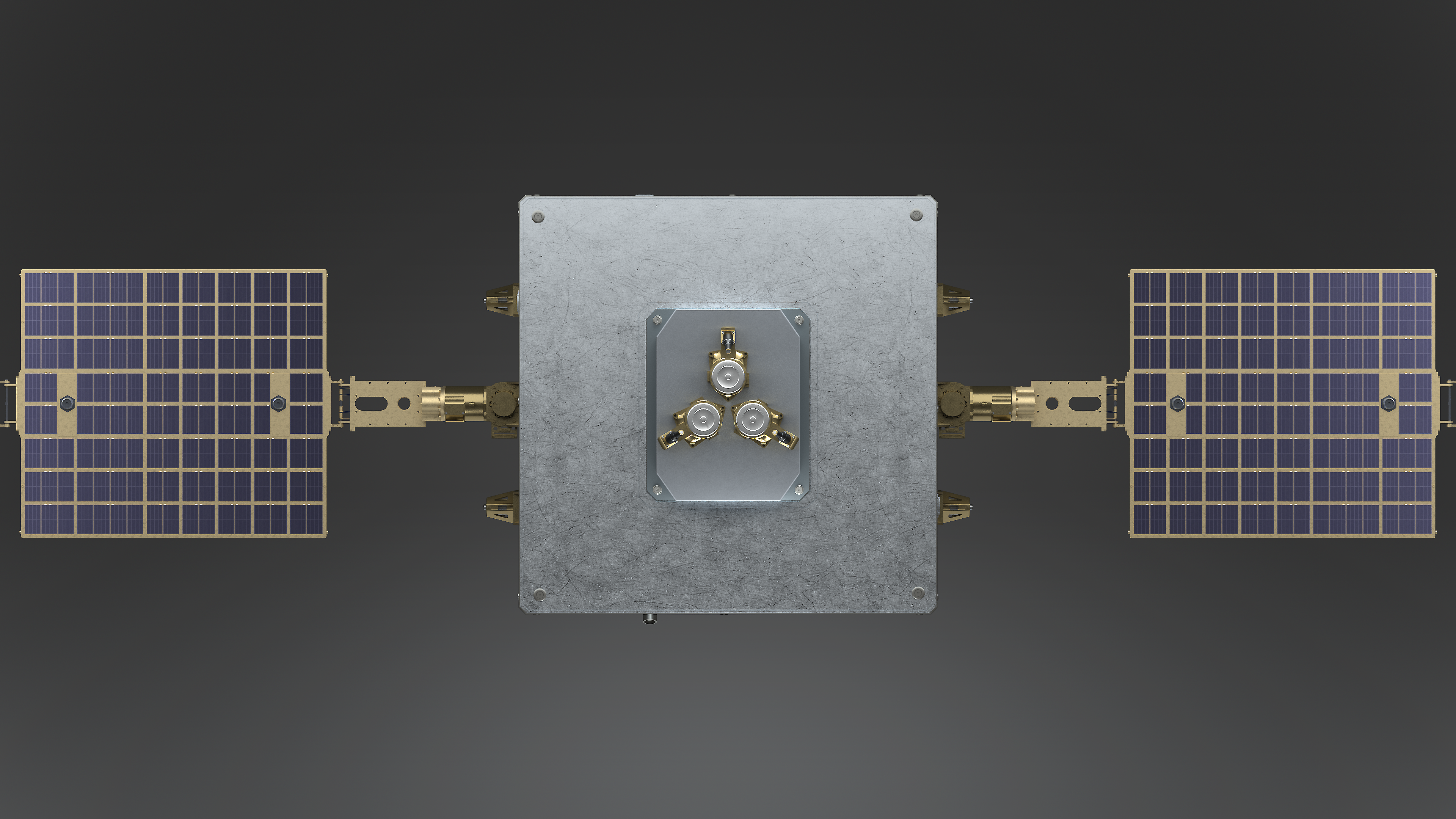
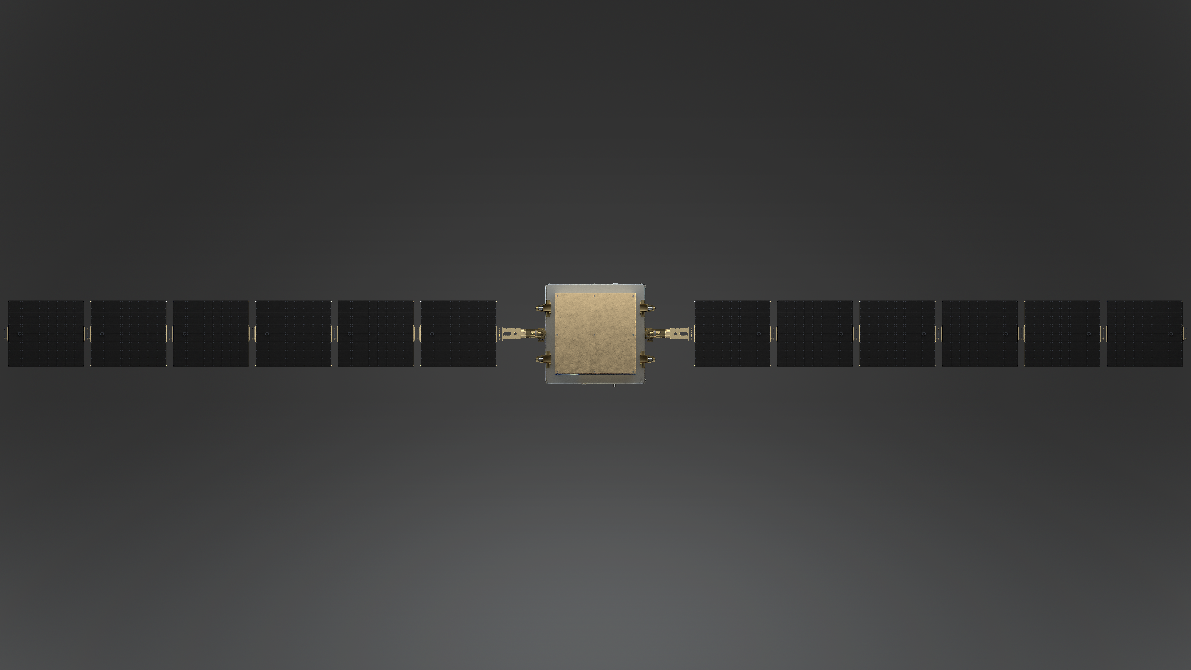
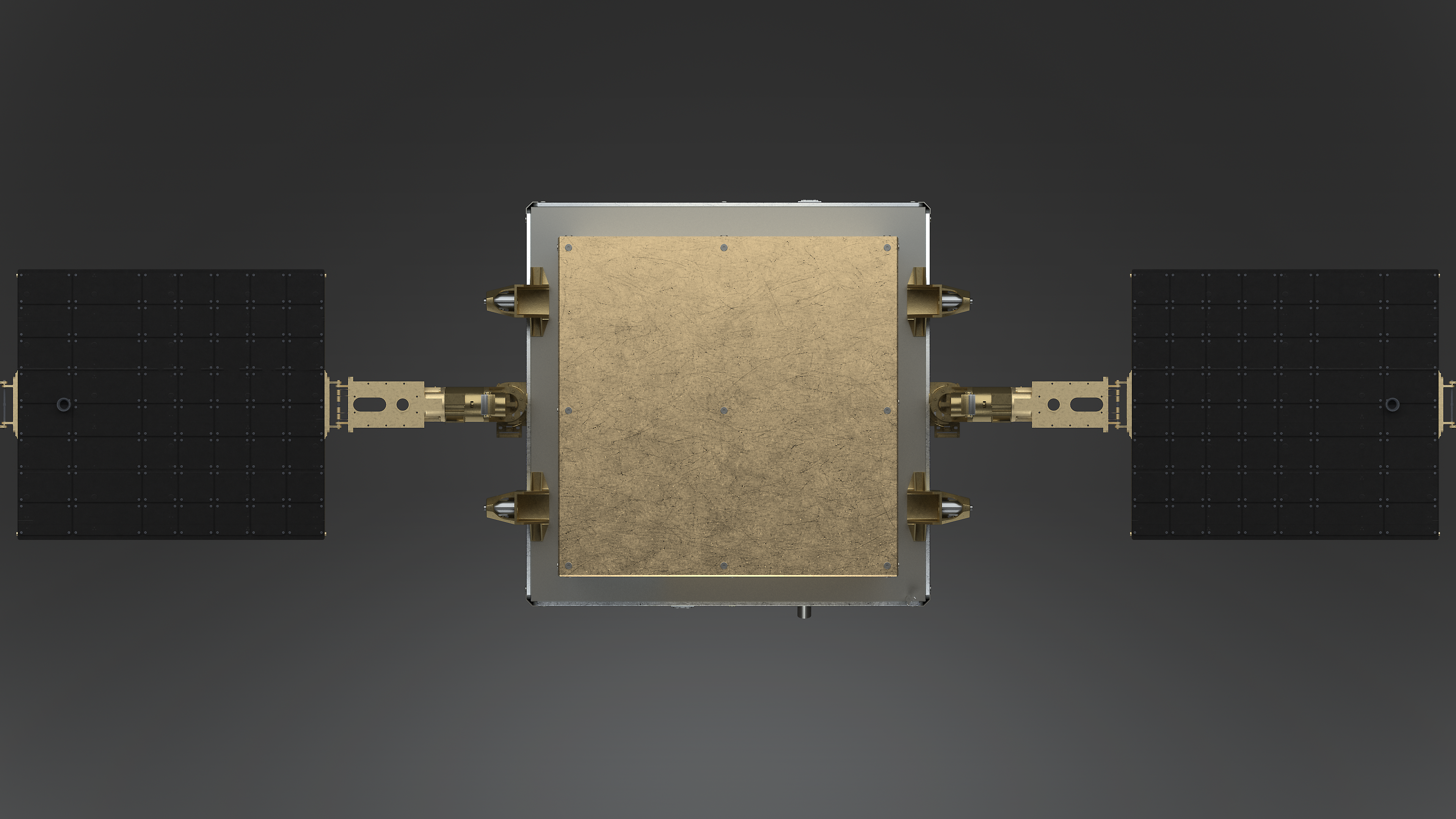
PIONEER's external configuration plate consolidates the spacecraft's primary orthographic views with isolated bus and solar-array studies. The seven-view schematic documents deployed span, bus envelope, array thickness, cell-facing surfaces, backing structure, and exterior attachment geometry as a single configuration reference.
 View Image Only
Isometric Systems Overview
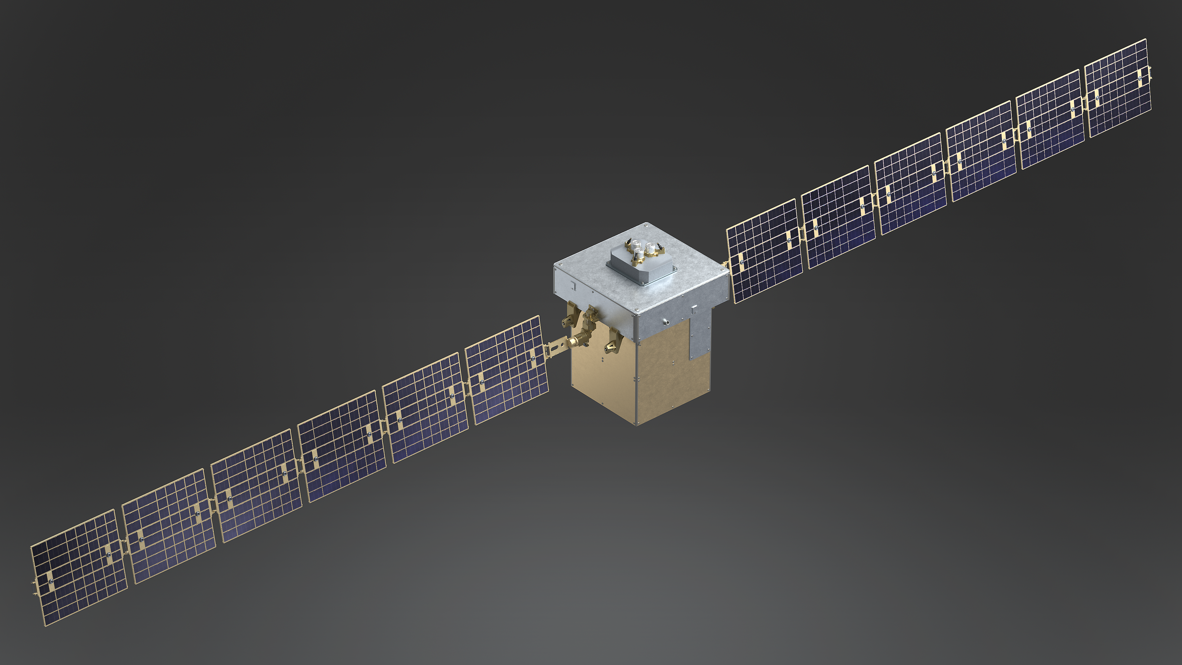
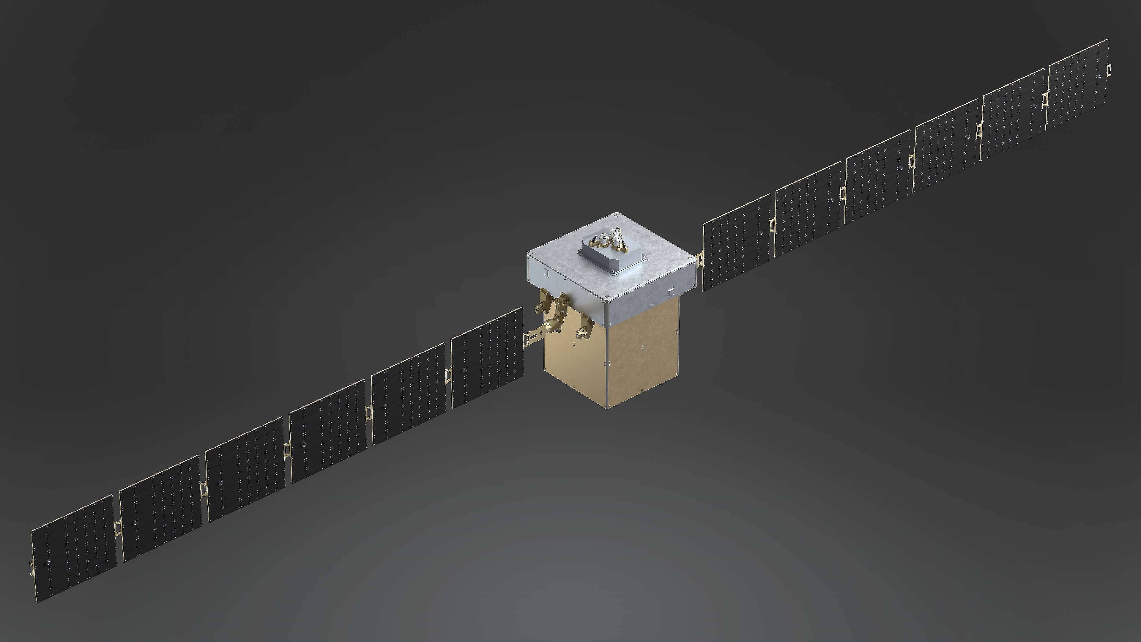
Front and rear isometric views establish the complete PIONEER configuration without perspective ambiguity. Together they identify the central service bus, upper equipment deck, lower mission module, array-drive hardware, deployment joints, and both the active and backing surfaces of the photovoltaic wings.
Annotation nomenclature follows standard spacecraft-engineering conventions and is based on the visible configuration of the supplied model.
Zenith and Nadir Configuration
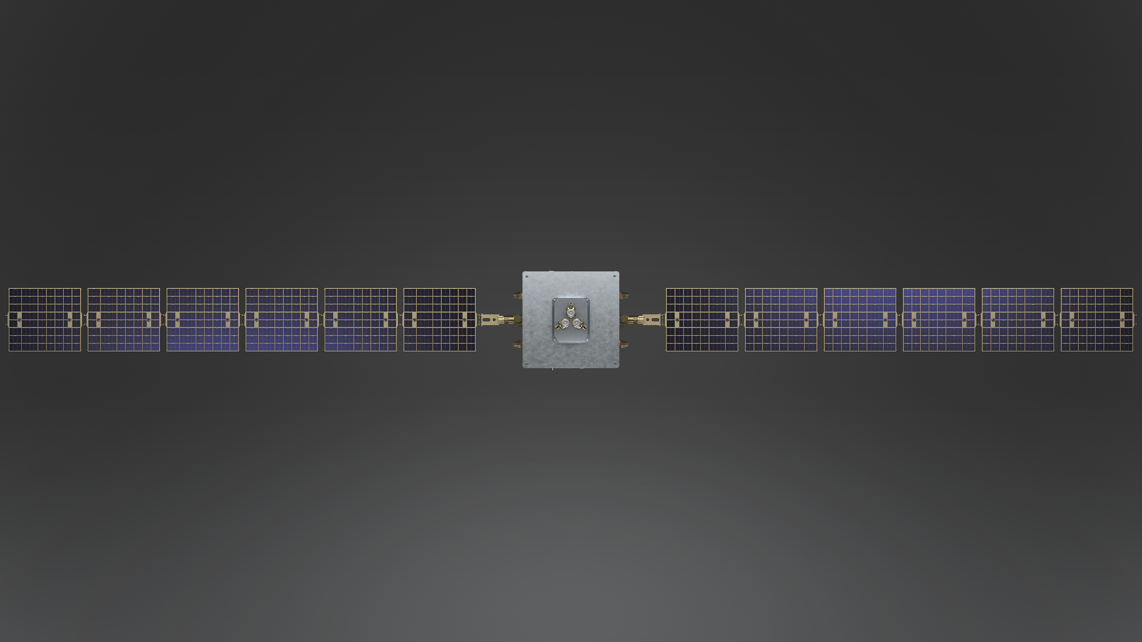
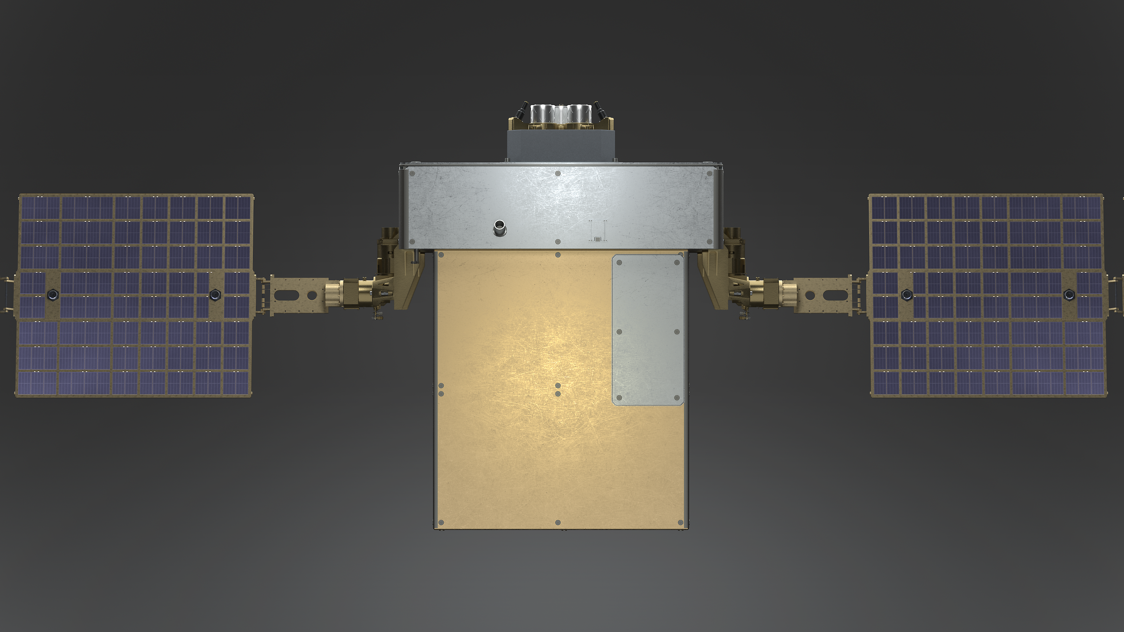
The opposing orthographic views document the full array footprint and the two working faces of the spacecraft. The zenith side carries the exposed upper equipment cluster and active photovoltaic surfaces; the nadir side presents the protected lower bus closeout and array backing structure. Close views preserve the interfaces that are difficult to evaluate at full span.
Elevation and Array Orientation
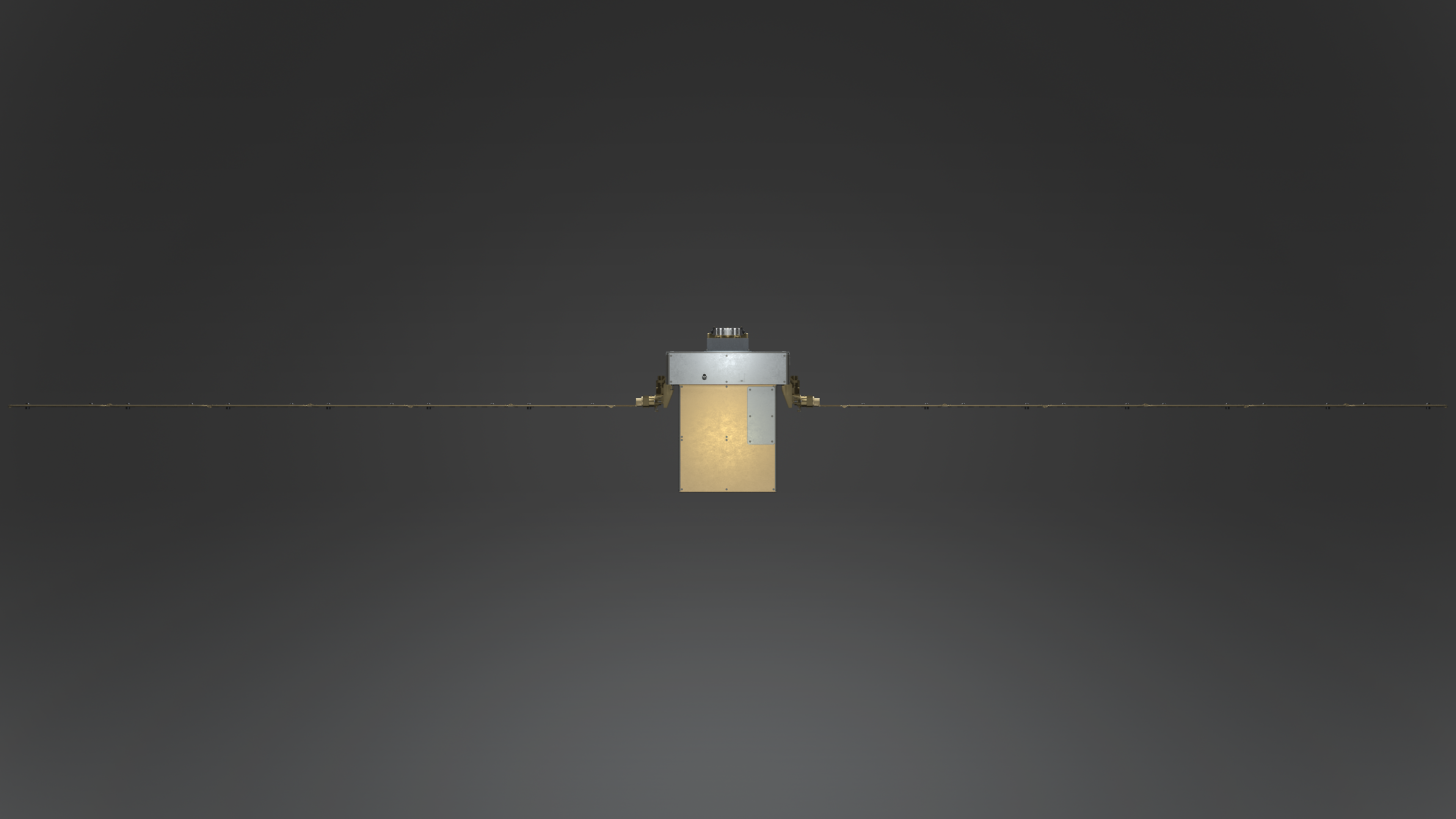
The elevation studies isolate PIONEER's cross section and demonstrate the rotational range of the array system. The edge-on configuration exposes the low-profile span and compact bus silhouette, while the rotated configuration presents the complete cell field for power-generation review. The close elevation resolves the stacked bus compartments and root hardware in greater detail.
Mission Campaign Visual
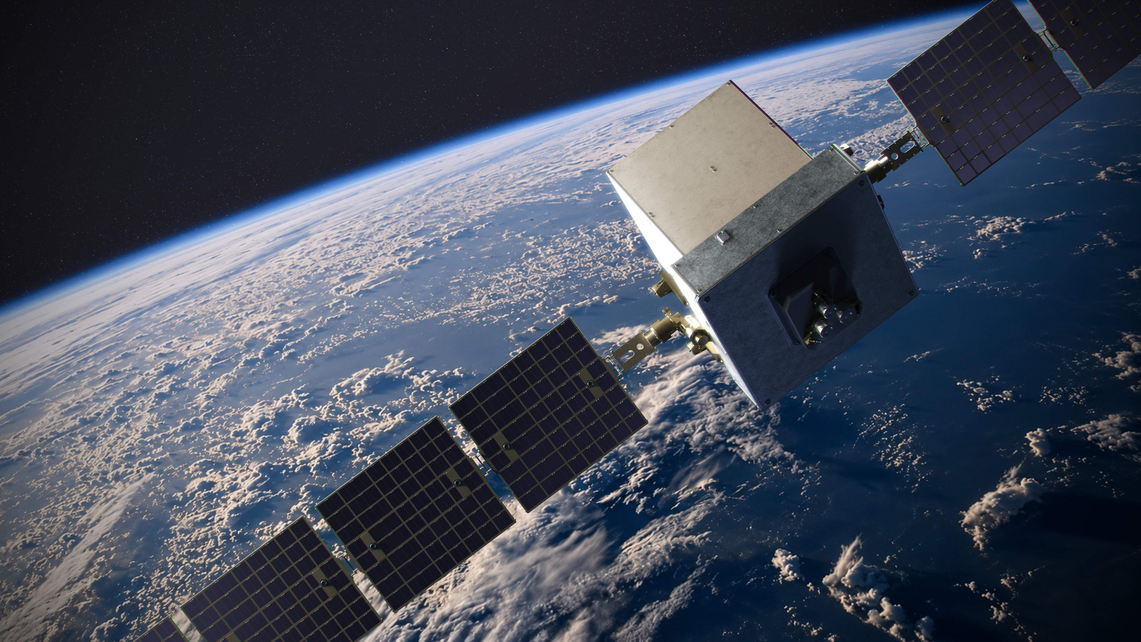
PIONEER's campaign image shifts from engineering review to mission communication. The closer perspective gives the spacecraft immediate scale and presence, while Earth, directional sunlight, and the extended array geometry reinforce a vehicle already at work in its intended environment.
The composition is designed to function across proposal covers, presentation openers, trade-show graphics, launch communications, and outward-facing campaign material without losing the identity of the spacecraft itself.
Visual Communication System
PIONEER's visual system is organized as a unified mission package rather than a disconnected render gallery. Operational imagery establishes context and scale; technical plates communicate configuration and visible hardware; and the campaign image turns the engineering character of the vehicle into a clear public-facing identity.
The result is a presentation language that can move between engineering review, program communication, and campaign use while keeping the spacecraft accurate, legible, and visually consistent.